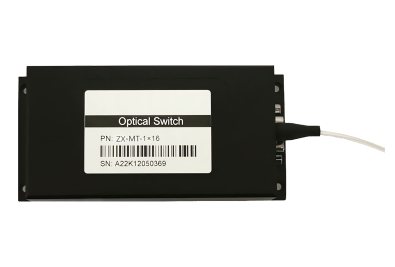
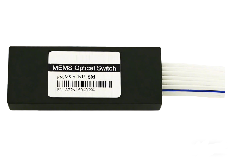
MEMS Optical Switch 1*N Multimode
WXG Optics' 1×N multimode MEMS optical switch adopts advanced micro-electromechanical system (MEMS) technology, featuring small package, high stability, high reliability and non-latching design. Support customizable 1×2/1×4/1×8/1×16 channel configurations, with optional control interfaces (TTL/UART or I2C/UART) , perfectly adapted to fiber optic sensing, DWDM networks, channel monitoring and other industrial scenarios.
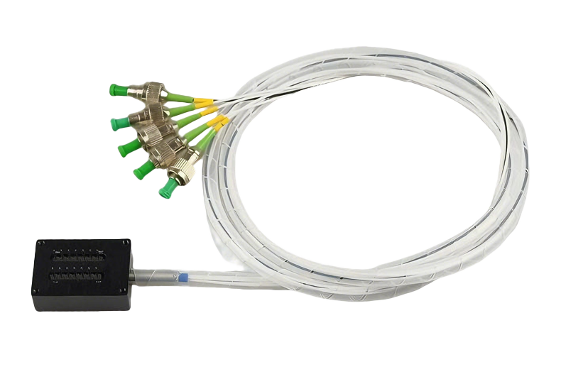
Customizable:Customizable 1*2/1*4/1*8/1*16
 Dongz
Email: Sales@wxgphotonics.com
Dongz
Email: Sales@wxgphotonics.com

Features
- MEMS technology.
- Small package.
- High stability, high reliability.
- Non-latching.
Applications
- DWDM networks.
- Channel monitoring.
- R&D in laboratory.
- Configurable OADM.
Specifications
| Parameters | MS-A-1xN-MM (N≤16) |
|---|---|
| Wavelength Range (nm) | 850±20 or 980±20 or 1310±20 or 1550±20 |
| Test Wavelength (nm) | 850 or 980 or 1310 or 1550 |
| Insertion Loss ¹,²,³, (dB) | Typ.: 0.6 Max.: 1.0 N=2~8Typ.: 1.0 Max.: 1.2 N=9~16 |
| WDL 2,4 (dB) | ≤0.3 |
| Return Loss 1,2 (dB) | ≥25 |
| Crosstalk 1,2,3 (dB) | ≥30 |
| Repeatability 5 (dB) | ≤±0.05 |
| Power Supply (V) | 5±0.25 |
| Power Consumption (mW) | ≤500 |
| Durability (cycle) | ≥10^9 |
| Switch Time (ms) | ≤10 |
| Transmission Power (mW) | ≤500 |
| Operating Temperature (℃) | -5~+70 |
| Storage Temperature (℃) | -40~+85 |
| Dimension (mm) | 65(L) x 24.7(W) x 15(H) ±0.2 |
Note:
1. Within operating temperature and SOP.
2. Excluding connectors.
3. Power off isolation same as cross-talk.
4. WDL is specified in ±40nm of 1310nm, at 23℃.
5. Repeatability is defined after 100 cycles.
PIN Definition
TTL / UART
| Pin | Signal | Description | I/O | Specification |
|---|---|---|---|---|
| 1 | D5 | Data 5 input | IN | TTL / LVTTL |
| 2 | VCC | DC power supply | Power | 5±0.25 VDC |
| 3 | /STROBE | Strobe signal, the falling edge of the effective | IN | TTL / LVTTL |
| 4 | GND | Ground | Power | |
| 5 | D0 | Data 0 input | IN | TTL / LVTTL |
| 6 | D1 | Data 1 input | IN | TTL / LVTTL |
| 7 | D2 | Data 2 input | IN | TTL / LVTTL |
| 8 | NC | No connect | ||
| 9 | TXD | UART serial data output | OUT | TTL / LVTTL |
| 10 | RXD | UART serial data input | IN | TTL / LVTTL |
| 11 | GND | Ground | Power | |
| 12 | D4 | Data 4 input | IN | TTL / LVTTL |
| 13 | D3 | Data 3 input | IN | TTL / LVTTL |
| 14 | /RESET | Active-low reset | IN | TTL / LVTTL |
I²C / UART
| Pin | Signal | Description | I/O | Specification |
|---|---|---|---|---|
| 1 | NC | No connect | ||
| 2 | VCC | DC power supply | Power | 5±0.25 VDC |
| 3 | NC | No connect | ||
| 4 | GND | Ground | Power | |
| 5 | A0 | I²C address A0 | IN | TTL / LVTTL |
| 6 | SDA | I²C data | IN | TTL / LVTTL |
| 7 | SCL | I²C clock | IN | TTL / LVTTL |
| 8 | NC | No connect | ||
| 9 | TXD | UART serial data output | OUT | TTL / LVTTL |
| 10 | RXD | UART serial data input | IN | TTL / LVTTL |
| 11 | GND | Ground | Power | |
| 12 | NC | No connect | ||
| 13 | A1 | I²C address A1 | IN | TTL / LVTTL |
| 14 | /RESET | Active-low reset | IN | TTL / LVTTL |
Optical Route

Dimension
Unit: mm

Ordering Information
MS-A-1xN-①-②-③-④-⑤-⑥
| N | ① | ② | ③ | ④ | ⑤ | ⑥ |
|---|---|---|---|---|---|---|
| Output Number | Fiber | TestWavelength | Tube | Fiber Length(include connector) | Connector | Interface |
| 8: 8 16:16 XX: other | M5: 50/125 M6: 62.5/125 XX: other | 85: 850nm 98: 980nm 31: 1310nm 55: 1550nm XX: other | 25: 250μm 90: 900μm | 05: 0.5m±5cm 10: 1.0m±5cm 15: 1.5m±5cm XX: other | NO: none FA: FC/APC FP: FC/PC LA: LC/APC LP: LC/PC SA: SC/APC SP: SC/PC XX: other | TTL:TTL/UART I2C:I²C/UART |